nslookup is command-line tool for querying the Domain Name System (DNS) to obtain domain name or IP addressmapping or for any other specific DNS record
Syntax:
C:\Users\User1>nslookup ?
Usage:
nslookup [-opt ...] # interactive mode using default server
nslookup [-opt ...] - server # interactive mode using 'server'
nslookup [-opt ...] host # just look up 'host' using default server
nslookup [-opt ...] host server # just look up 'host' using 'server'
nslookup can be used to find the query using a different server than the default dns server.
>nslookup forexample.com 8.8.8.8 - here the 8.8.8.8 is the public google dns.
Showing posts with label Networking/ Cisco. Show all posts
Showing posts with label Networking/ Cisco. Show all posts
Tuesday, 12 November 2013
Friday, 18 October 2013
How to add a route of a destination ip when you have multiple network cards or gateway
route -p ADD <Destination> MASK 255.255.255.255 <Gateway>
eg: route -p ADD 192.168.1.0 MASK 255.255.255.0 192.168.10.1
In this case the route looking for 192.168.1.0 network will pass through the gateway 192.168.10.1
route print - To display the entire contents of the IP routing table.
route delete 192.168.1.0 mask 255.255.255.0
Saturday, 12 October 2013
EtherChannel in Cisco Switches
An ether channel consists of individual fast Ethernet or gig Ethernet links bundled into a single logical link. It provides fault-tolerant high-speed links among switches, routers and servers.

Switch>en
Switch#config
Configuring from terminal, memory, or network [terminal]? t
Enter configuration commands, one per line. End with CNTL/Z.
Switch(config)#hostname switch0
switch0(config)#interface range fastEthernet 0/1-4
switch0(config-if-range)#channel-protocol pagp
switch0(config-if-range)#channel-group 1 mode auto
switch0(config-if-range)#
Creating a port-channel interface Port-channel 1
%LINEPROTO-5-UPDOWN: Line protocol on Interface FastEthernet0/1, changed state to down
%LINEPROTO-5-UPDOWN: Line protocol on Interface FastEthernet0/1, changed state to up
%LINEPROTO-5-UPDOWN: Line protocol on Interface FastEthernet0/2, changed state to down
%LINEPROTO-5-UPDOWN: Line protocol on Interface FastEthernet0/2, changed state to up
%LINEPROTO-5-UPDOWN: Line protocol on Interface FastEthernet0/3, changed state to down
%LINEPROTO-5-UPDOWN: Line protocol on Interface FastEthernet0/3, changed state to up
%LINEPROTO-5-UPDOWN: Line protocol on Interface FastEthernet0/4, changed state to down
%LINEPROTO-5-UPDOWN: Line protocol on Interface FastEthernet0/4, changed state to up

Switch>en
Switch#config
Configuring from terminal, memory, or network [terminal]? t
Enter configuration commands, one per line. End with CNTL/Z.
Switch(config)#hostname switch0
switch0(config)#interface range fastEthernet 0/1-4
switch0(config-if-range)#channel-protocol pagp
switch0(config-if-range)#channel-group 1 mode auto
switch0(config-if-range)#
Creating a port-channel interface Port-channel 1
%LINEPROTO-5-UPDOWN: Line protocol on Interface FastEthernet0/1, changed state to down
%LINEPROTO-5-UPDOWN: Line protocol on Interface FastEthernet0/1, changed state to up
%LINEPROTO-5-UPDOWN: Line protocol on Interface FastEthernet0/2, changed state to down
%LINEPROTO-5-UPDOWN: Line protocol on Interface FastEthernet0/2, changed state to up
%LINEPROTO-5-UPDOWN: Line protocol on Interface FastEthernet0/3, changed state to down
%LINEPROTO-5-UPDOWN: Line protocol on Interface FastEthernet0/3, changed state to up
%LINEPROTO-5-UPDOWN: Line protocol on Interface FastEthernet0/4, changed state to down
%LINEPROTO-5-UPDOWN: Line protocol on Interface FastEthernet0/4, changed state to up
Switch>en
Switch#config t
Enter configuration commands, one per line. End with CNTL/Z.
Switch(config)#hostname switch1
switch1(config)#interface range fastEthernet 0/1-4
switch1(config-if-range)#channel-protocol pagp
switch1(config-if-range)#channel-group 1 mode desirable
switch1(config-if-range)#
Creating a port-channel interface Port-channel 1
%LINEPROTO-5-UPDOWN: Line protocol on Interface FastEthernet0/1, changed state to down
%LINEPROTO-5-UPDOWN: Line protocol on Interface FastEthernet0/1, changed state to up
%LINEPROTO-5-UPDOWN: Line protocol on Interface FastEthernet0/2, changed state to down
%LINEPROTO-5-UPDOWN: Line protocol on Interface FastEthernet0/2, changed state to up
%LINEPROTO-5-UPDOWN: Line protocol on Interface FastEthernet0/3, changed state to down
%LINEPROTO-5-UPDOWN: Line protocol on Interface FastEthernet0/3, changed state to up
%LINEPROTO-5-UPDOWN: Line protocol on Interface FastEthernet0/4, changed state to down
%LINEPROTO-5-UPDOWN: Line protocol on Interface FastEthernet0/4, changed state to up
%LINK-5-CHANGED: Interface Port-channel 1, changed state to up
%LINEPROTO-5-UPDOWN: Line protocol on Interface Port-channel 1, changed state to up
DHCP Configuration on Cisco Switch 3560
Switch>en
Switch#config t
Enter configuration commands, one per line. End with CNTL/Z.
Switch(config)#ip dhcp pool DHCP_Server
Switch(dhcp-config)#network 192.168.1.0 255.255.255.0
Switch(dhcp-config)#default-router 192.168.1.1
Switch(dhcp-config)#exit
Switch(config)#ip dhcp excluded-address 192.168.1.1 192.168.1.50
Switch(config)#exit
Switch#
%SYS-5-CONFIG_I: Configured from console by console
Switch#copy run start
Destination filename [startup-config]?
Building configuration...
[OK]
Switch#
Switch#config t
Enter configuration commands, one per line. End with CNTL/Z.
Switch(config)#ip dhcp pool DHCP_Server
Switch(dhcp-config)#network 192.168.1.0 255.255.255.0
Switch(dhcp-config)#default-router 192.168.1.1
Switch(dhcp-config)#exit
Switch(config)#ip dhcp excluded-address 192.168.1.1 192.168.1.50
Switch(config)#exit
Switch#
%SYS-5-CONFIG_I: Configured from console by console
Switch#copy run start
Destination filename [startup-config]?
Building configuration...
[OK]
Switch#
Tuesday, 1 October 2013
VPN Client access on Cisco Router
Setting up a VPN client access on RV042 Cisco router
Login to the router from the browser, go to VPN, VPN Client Access. Add a new client


Please enter the created username and password. Also the public ip on the Cisco router and press connect.

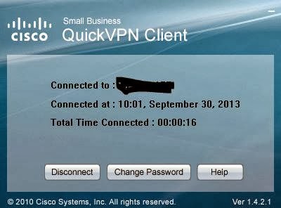

http://software.cisco.com/download/release.html?mdfid=282414013&softwareid=282465795&release=1.4.2.1
Monday, 9 September 2013
Port forwarding in Cisco Router RV042
Login to the router from a web interface, if its the default ip(192.168.1.1) prompt for a username and password(default is admin/admin). Once logged in go to Setup, click on forwarding, there you can see the options to add a new service. The service we are adding is RDP for windows XP/7.


Sunday, 8 September 2013
Configure VoIP in your Cisco SPA122 adapter
You can use an SPA 122 adapter to setup your own voip phone. You have to get a DID number from a provider and configure it on the voip adpter. To configure it on the SPA 122 follow the step after getting the DID number.
The default ip to access voip adapter is http://192.168.15.1
Connect the computer to use DHCP and connect it to the yellow port of the voip adapter.
access http://192.168.15.1 from your internet browser or any other browser. You will be prompt to enter the username and password. Enter admin/admin as username and password.


The default ip to access voip adapter is http://192.168.15.1
Connect the computer to use DHCP and connect it to the yellow port of the voip adapter.
access http://192.168.15.1 from your internet browser or any other browser. You will be prompt to enter the username and password. Enter admin/admin as username and password.

Once you enter the username /password you will be on the quick setup. Enter the following information provided by your DID provider and submit the changes. Keep the networking in bridge mode if you are connected to a router that is providing the ip address.


Wednesday, 5 September 2012


Monday, 5 September 2011
How to Reset Watchguard Firebox Edge to Factory Default
To set the Firebox X Edge e-Series to the factory default settings:
Disconnect the power supply.
Hold down the Reset button on the rear side of the Edge.
Connect the power supply while you continue to hold down the Reset button.
Continue to hold down the button until the yellow Attn light stays on. This shows you that the Edge was successfully restored to the factory default settings.
This process can take 45 seconds or more.
Do not try to connect to the Edge at this time. You must start the Edge one more time, as the subsequent steps show. If you do not start the Edge one more time, when you try to connect to the Edge you will see a web page that shows the message, “Your WatchGuard Firebox X Edge is running from a backup copy of firmware.” You could also see this message if the Reset button is stuck in the depressed position. If you continue to see this page, check the Reset button, and start the Edge again.
Hold down the Reset button on the rear side of the Edge.
Connect the power supply while you continue to hold down the Reset button.
Continue to hold down the button until the yellow Attn light stays on. This shows you that the Edge was successfully restored to the factory default settings.
This process can take 45 seconds or more.
Do not try to connect to the Edge at this time. You must start the Edge one more time, as the subsequent steps show. If you do not start the Edge one more time, when you try to connect to the Edge you will see a web page that shows the message, “Your WatchGuard Firebox X Edge is running from a backup copy of firmware.” You could also see this message if the Reset button is stuck in the depressed position. If you continue to see this page, check the Reset button, and start the Edge again.
Disconnect the power supply.
Connect the power supply again.
The Power Indicator is on and your Edge is reset.
Connect the power supply again.
The Power Indicator is on and your Edge is reset.
Once it's reset, you can use 192.168.111.1 to access the firebox.
By default the read password is readonly and configuration password is readwrite
By default the read password is readonly and configuration password is readwrite
Sunday, 5 September 2010
Watchguard Firebox Edge Factory Default Configuration
Trusted network
The default IP address for the trusted network is 192.168.111.1. The subnet mask for the trusted network is 255.255.255.0.
The Firebox X Edge is configured to give IP addresses to computers on the trusted network through DHCP. By default, the IP addresses given can be from 192.168.111.2 to 192.168.111.254.
External network
The Firebox is configured to get an IP address with DHCP.
Optional network
The optional network is disabled.
Firewall settings
All incoming policies are denied. The outgoing policy allows all outgoing traffic. Ping requests received on the external network are denied.
System Security
The Firebox X Edge e-Series administrator account is set to the default user name of “admin” and the default passphrase of “admin.” When you connect to the Edge, the Quick Setup Wizard includes a dialog box for you to set the administrator account user name and passphrase. After you complete the Quick Setup Wizard, you must use the user name and password that you selected to see the configuration pages.
The Firebox X Edge is set up for local management from the trusted network only. Additional configuration changes must be made to allow administration from the external network.
Upgrade Options
Upgrade options such as WebBlocker, spamBlocker, and Gateway AV/IPS are always available. You must type the feature keys into the configuration page or use the feature key synchronization feature to activate upgrade options. If you restore the Firebox X Edge to its factory default settings, you do not have to type the feature keys again.
Tuesday, 10 August 2010
installing gns3 on ubuntu
1. sudo apt-get install dynagen python-qt4
2. cd /opt
sudo wget http://space.dl.sourceforge.net/project/gns-3/GNS3/0.7.2/GNS3-0.7.2-src.tar.bz2
sudo tar -xjvf GNS3-0.7.2-src.tar.bz2 && rm GNS3-0.7.2-src.tar.bz2
sudo mv GNS3-0.7.2-src /opt/GNS3
2. cd /opt
sudo wget http://space.dl.sourceforge.net/project/gns-3/GNS3/0.7.2/GNS3-0.7.2-src.tar.bz2
sudo tar -xjvf GNS3-0.7.2-src.tar.bz2 && rm GNS3-0.7.2-src.tar.bz2
sudo mv GNS3-0.7.2-src /opt/GNS3
Sunday, 9 August 2009
A linux machine can be used as a router.
A linux machine can be used as a router.
eg:
you have a system with class A ip address and another system with class B ip address, in that case a linux system can be used to connect these two systems and this system will act as a router.
nodeA: 172.168.1.1
nodeB: 10.10.1.1
the router system should be configured with two or three virtual ipaddress.
one with 10.10.1.2 and another with 172.168.1.2
nodeA: nodeC : node B
Assign the node C with 192.168.1.8
#netconfig -d eth0
then again assign the node C with 2 virtual ip
#netconfig -d eth0:1 ->10.10.1.2
#netconfig -d eth0:2 ->172.168.1.2
assign these two virtual ip as the gateway ip for node A and node B
Assign node A with
#netconfig -d eth0
172.168.1.1 with gateway as 172.168.1.2
Assign node B with
#netconfig -d eth0
10.10.1.1 with gateway as 10.10.1.2
In node C
#vi /etc/sysctl.conf
and replace the line
net.ipV4.ip_forward =0 with net.ipV4.ip_forward =1
#sysctl -p
#service network restart
you have a system with class A ip address and another system with class B ip address, in that case a linux system can be used to connect these two systems and this system will act as a router.
nodeA: 172.168.1.1
nodeB: 10.10.1.1
the router system should be configured with two or three virtual ipaddress.
one with 10.10.1.2 and another with 172.168.1.2
nodeA: nodeC : node B
Assign the node C with 192.168.1.8
#netconfig -d eth0
then again assign the node C with 2 virtual ip
#netconfig -d eth0:1 ->10.10.1.2
#netconfig -d eth0:2 ->172.168.1.2
assign these two virtual ip as the gateway ip for node A and node B
Assign node A with
#netconfig -d eth0
172.168.1.1 with gateway as 172.168.1.2
Assign node B with
#netconfig -d eth0
10.10.1.1 with gateway as 10.10.1.2
In node C
#vi /etc/sysctl.conf
and replace the line
net.ipV4.ip_forward =0 with net.ipV4.ip_forward =1
#sysctl -p
#service network restart
by doing this the node A can communicate with node B thru' node C
Subscribe to:
Posts (Atom)